
Two months ago, I posted drawings for a set of modular Infinity buildings. I took some time off after that to paint my Space Mans, but now I’ve come back to my beloved Space Buildings and gotten them to a point where they’re playable and somewhat bloggable.
For those who need a refresher, here’s basically what I’m building:

The terrain set is designed to represent a series of temporary, pre-fabricated buildings that can be used to represent new colonies or research installations. The buildings use a standardized connector to let pieces be joined together in any number of combinations, ensuring that the terrain doesn’t get stale to play on.
So, let’s see what I’ve knocked together so far. 🙂
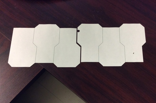
I did the first stages of planning and design during about a week of lunches at work. I drew up the designs in Adobe Illustrator, and then cut them out on paper to give me templates to trace around. It was very important throughout this project to do everything with precision and careful measurement; the roofs and floors were built two months before the walls, and everything was mass-produced in large batches for efficiency’s sake, so I needed to be sure that I was building everything according to fairly exact measurements, or else things wouldn’t have fit together when I got around to final assembly.
This meant precision at all stages: precise plans on the computer, precise cutting out of templates, precise transfer onto foamcore, precise cutting of panels, and precise cutting of bends and corners. If at any point I let myself get sloppy out of boredom, I’d either end up with crappy terrain that doesn’t fit together, or a lot of time wasted re-doing work at the end.
Neither was an acceptable outcome.

While I was working on the designs, I happened to stop by the book store at the college where I work and discovered that they stock a full range of drafting materials for the graphic design students; a quick shopping trip later, I walked back to my office with foamcore, knives, pushpins, rulers, and glue. Thus armed, another week of lunches was put into producing floor and roof panels
I wanted to get as many panels as I could out of each foamcore sheet, so I traced each one directly touching its neighbors; this would also save me time when cutting, as cutting the top of one panel would give me the bottom of the next one. The paper templates were held onto the foamcore with pushpins to avoid slipping while I traced.

Each panel was coded to help me track what it was and whether its mate had been built yet.The first letter tells me what type of piece it is (E = “end”; M = “mid”; B = “bend”; H = “hub”), the number tells me how many of that type I’ve built, and the last letter tells me whether it’s the top or bottom (not really a huge deal, other than for the purposes of ensuring that I had two panels for each piece).
The codes were tracked in a Google spreadsheet:
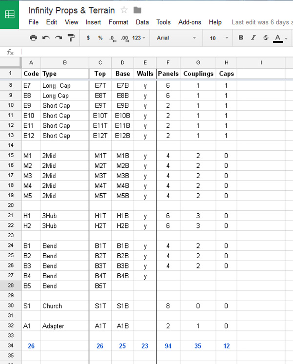
This sheet will continue to be useful later on when I start working on gluing paneling onto the buildings, as it tells me exactly how many roof panels I need to cut out (94); I can also extrapolate to figure out how many windows I’ll need (half the number of roof panels, minus the number of ladders (which will be one per Mid piece– probably around 45).
BECAUSE SPUD LOVES MATH, THAT’S WHY.

And then the cutting began. I got some funny looks from coworkers.

As pieces came out of the assembly line over the course of a few days, I piled them up on my desk.

I was able to use about 90% of the first foamcore sheet by putting in a variety of panel shapes.

The second one had a bit more waste because it contained the 3-way hubs and the 60-degree bend pieces, which didn’t fit together as nicely.
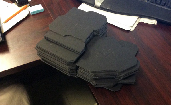
Cut cut cut, stack stack stack.

After a week or two, I had what looked like a good pile of top and bottom panels; I wasn’t sure how many I’d ultimately need, though, so I brought them to my local store to lay them out and see how much space they took up.

Not bad, but I’d definitely need more. I ultimately cut up one more foamcore sheet’s worth of panels to give me 24 pieces in total; these nicely filled out the remaining empty portions of a 4×4, so I called this phase of the project done and moved onto the walls.

To build these, I cut a full foamcore sheet up into 3″ strips. This phase took place on my mom’s dining room table while I was visiting for the weekend; I made a cutting mat out of some overturned placemats so that she wouldn’t beat me to death with a candlestick.

I spent some time measuring various panels to figure out how long the wall segments should be; I measured the same point on multiple pieces to account for any slight wobbles in my cutting. In the end, these basic Mid pieces turned out to be entirely made up of 50mm and 18mm faces.

Deciding how many pieces to divide the walls into is fairly straightforward. All folds in a sheet of foamcore require cutting, and it’s a pain in the ass to draw the lines for those cuts precisely on two sides of a foamcore sheet. Therefore, I would connect faces together that folded all in the same direction, and then stopped when the outline turned the other way. For these simple mid pieces, that meant four wall pieces: two for the corners, and two for the bigger “bubbles”.
Here’s quick video I made to explain how I divided wall segments and also how I made the necessary cuts to produce 90-degree and 45-degree folds in the foamcore:
For those who have always dreamed of spending twelve minutes staring fixedly at the Crotch of Spud in glorious HD without being judged by society, today is the day your most desperate desires are finally made real.
You’re welcome.

Once those pieces were done, they were ready for gluing!

This part is pretty straightforward– I’d put a bead of glue all around the edge of the floor panel on the area that one wall piece would take up, then drop the wall piece into place. Then more glue down the edge of the first wall and along the floor position of the NEXT wall piece, and drop that in.

And so on, and so forth, until all the walls are in place.
On this first test piece I made a slight mis-measurement and ended up with about a 1mm gap. Problems like this are why I always do one complete object by hand before proceeding to mass production; I can correct for any errors that pop up in the prototype and ensure that they don’t plague the remaining pieces. In this case, I just made a slight extension of one wall piece templates, and the remaining pieces were good to go. 🙂
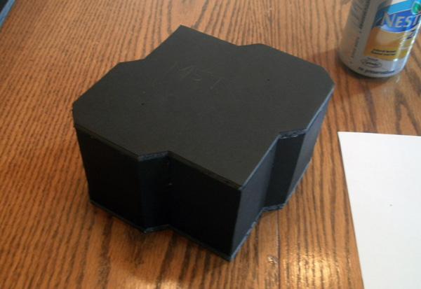
Once all the walls are down, you just throw some glue around the top rim, and drop the roof on to close it up.
Satisfied with my prototype, I proceeded with mass production.

I went back into Illustrator and made some paper templates to help me quickly mark the panels on my foamcore sheets (the lines are on the other side in this shot). I cut out notches at the top and bottom of each piece to let me make tick marks where the panel divisions would go.
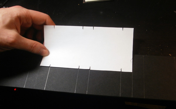
These were then traced onto the previously-made 3″ foamcore strips; ticks were made all along the strip, which were then connected with a ruler.
After that, the construction is the same as above, leaving me at the end of two productive evenings with my first connecting pieces:
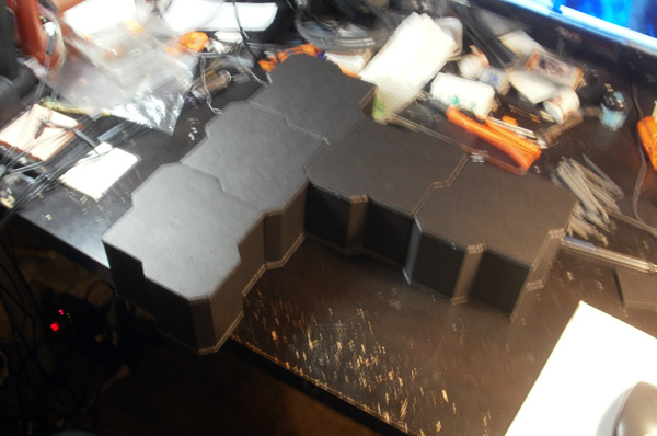
BOO-YEAH! 🙂
The mid pieces were the simplest to build; for the remaining pieces, I’d move up through the other shapes in increasing order of difficulty/pain-in-the-assitude.

By that metric, the next item up for production was the pair of 3-way hubs. These were pretty simple to build, each consisting of three 50mm sides set 90 degrees apart, with three smaller bubbles between them. I was able to cut these out entirely using the tracing templates from the mid pieces.
Cut cut cut, score score score…

…glue glue glue.

ERMAGERD IT’S STARTING TO COME TOGETHER

After the hubs, I worked on the 60-degree bends. There are four of these, and they have much less regular geometry than the previous pieces; each would need to be built out of five separate panel pieces of wildly differing sizes, many of which contained both 90-degree and 45-degree folds on the same wall segment.
Despite this complexity, I confidently cut up the walls for all four of them without assembling one as a trial; this is where my commitment to precision was paying off, as I knew the pieces I was measuring would line up as long as I continued to measure everything carefully and cut as cleanly as possible.

MOAR GLUE

ZOMG SO PRETTY

By this point, I was starting to build up a pretty formidable pile of foam chunks on my desks, each representing the volume that I’d removed from a single foamcore fold. I’ve always enjoyed piling up large quantities of garbage as a sort of progress indicator, for reasons that I’ve never really been able to explain. This one was fairly harmless, but it was somewhat less amusing (to my parents, at least) when they showed up to move me out of my university apartment and found that I had diligently piled up all 43 empty cases of soda I’d consumed that year.
“Cool, huh?” said a Spud who was about to get smacked in the side of the head.
Look, let’s not pretend that any of us were under the illusion that Spud was a rational human being. We’re all a bit too far into this mess for phony looks of shock.

The last pieces to assemble were the end caps, and these would be by far the most time-consuming. While their walls were composed of very simple shapes (even simpler than the Mid pieces), these end caps all needed doors, stairs, and balconies built into them. I had originally been planning to add all of these details later on in the detailing stage, but realized that it would be much harder to mount the doors onto a closed box where I can’t access the insides of the walls.
To make sure that the doors were all sized and positioned correctly, I rigged up a cut-out template that I could hold up against each piece to ensure correct spacing.
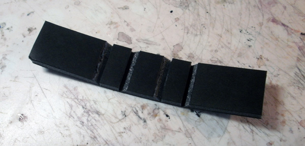
The doors are build just like the walls, albeit a bit smaller.
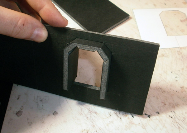
Incidental aside: in my original drawings, I had planned to have flat-mounted doors without any significant door frames. These were designed to be made quickly and simply stuck onto the outsides of the buildings. However, local heroin dealer Tom had his annual good idea when we were putting the pieces though a dry run game.
Our store has a pretty impressive array of MDF laser-cut Space Buildings, all of which have removable ceilings and floors to let you put models inside and have dramatic indoor shootouts. In practice, however, nobody actually does this. For one thing, it’s a pain in the ass to constantly remove and then replace the roof; and if there’s a different model actually standing on the roof, then it’s basically impossible to pick the roof up to put models underneath it. As a result, we don’t bother with removing roofs at all, even though nearly all of our terrain is capable of it– we just stand every model on the roof, and then put a D4 next to it to indicate which floor it’s standing on:

Dude on the left is on the ground floor. Dude on the right is on the roof.
The only part of the buildings’ interiors we actually make use of are the doorways. You don’t need to pull the building apart to nudge a model just inside a door, so we frequently park models there instead of using our “roof elevation proxy” system.
Tom pointed this out when I was discussing my ongoing construction efforts, and noted that even if I wasn’t going to make roofs that open (which he agreed is pointless), I should still cut the doors out so that models can be placed inside the way we do with the other buildings. His suggestion was just “holes in the walls”, which I feared would result in models falling inside and getting bounced around while we tried to retrieve them; however, it was a relatively simple modification to put a 1″ deep archway around each door with a backing panel and a floor, allowing us to slip a model inside to take cover without any worry about losing it.
And thus were the crap ideas of lesser beings polished into gold by the superior intellect of The Spud, and all was joyous throughout the land.
Spud be with you.

Wait…where we we again?
Oh, right. Door frames mounted to walls, walls mounted to floors.
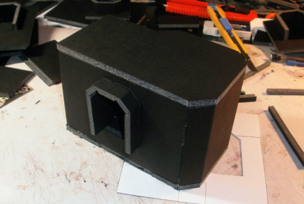
Roofs attached to close everything up.
Other incidental aside: The doors on all of these end pieces are raised 1″ off the ground. This was something that I came up with when I was drawing up the designs– I was thinking about how my vision for these buildings had been that they’re dropped from space into uncivilized locations, and how that likely meant that the #1 design consideration for them would be “hardiness”.
So as I drew, I pondered what they might have been designed to endure– locking doors to endure alien animal attacks; hardened paneling and retractable solar panels to weather sandstorms; and, thinking back to my own less-space-oriented life experiences, raised doors to resist floods. That’s one thing my family learned after our first spring flood– we stopped storing boxes directly on the floor of our basement, instead putting everything at least 4″ up on shelving units. The same thing, I reasoned, would help with these prefab buildings– by putting all openings a few feet up in the air, they would be less likely to take in water in the event of freakish alien rainstorms.
Also… the balconies looked cool.
That helped.
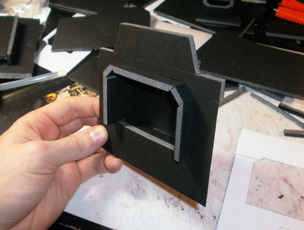
Not all of the end cap pieces would actually be end caps. Two of them were being adapted to form a bridge:

In order to give enough clearance for a standard Infinity model to pass underneath, the underside of the bridge needed to be at least 2″ up. My other doors had all started 1″ off the ground, but if I did that with the bridge pieces, I would need a very steep upward portion on the outsides to get from the door to the center of the span. That would look really stupid, so I raised the doors on the bridge piece so that they started half an inch higher.

This mostly worked, but presented a slight problem when I attached the roofs–

That being that the doors ended up taller than the rest of the buildings, requiring a cutout to fit.
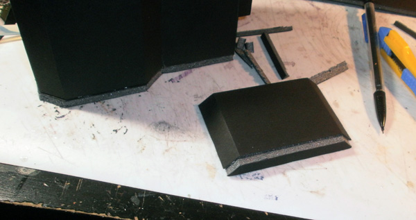
I solved this by making little caps to go over the cutouts.
The actual bridge span will be built a bit later along with all the balconies and stairs… more on those in a bit.
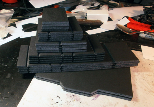
When I was cutting out roofs and floors, I produced two different sizes of end caps: short caps that were one “panel row” deep, and long caps that were three rows deep. An end cap that merely consists of a small door stuck in the face of the building doesn’t require much depth, but I also wanted to be able to have more complicated end pieces that ran through a few rows.

The first one I built ended up being, in retrospect, a complete waste of a long piece– because while it had a wider door…

…it wasn’t making any use at all of the extra rows of panels. I’m going to ponder this one a bit and probably modify it a bit to make better use of all of that empty roof space. Not sure yet what that’ll consist of– maybe a big skylight? A communication array? A rooftop garden?
Need to think about it more…

The next long end cap actually DOES make use of its length. This piece is supposed to be a garage, with a pair of wide doors that roughly match the height of some toy trucks I bought at a dollar store a few months back. These doors would be set into the SIDE of the building instead of the end.

It was a bit complicated to figure out where to cut the side panels to accommodate the doors; all of the other ones were mounted straight into a flat wall, but this one would have them cutting through a bumpy wall, joining up in the middle of an outward-poking bubble. I didn’t want to do all the math to figure out how much extra space to allow for the angles on the bubble, so instead, I used the outside edges of the doors as my landmark.
Measuring the door templates on the base piece, I found that they ended 8mm from the left side, 20mm from the right side, and 7mm from each other in the middle. I then transferred these measurements to the wall segment pieces. Thus, it didn’t matter how much longer the angle made the door frame– as long as the left and right edges fell in the right places, the horizontal cuts would just work out.

Because the doors on the garage directly touch the ground, it was easier to assemble it upside down, gluing the tops of the remaining wall pieces to the roof.
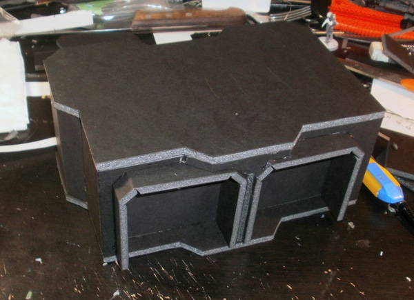
I then dropped the door frames in, turned it over, and glued it to the base.
This is probably my favourite piece from the whole kit– I love how the outward bulge looks over the two doors. 😀

The last type of long end cap, of which I’d be building two, was a combination door/rooftop staircase.
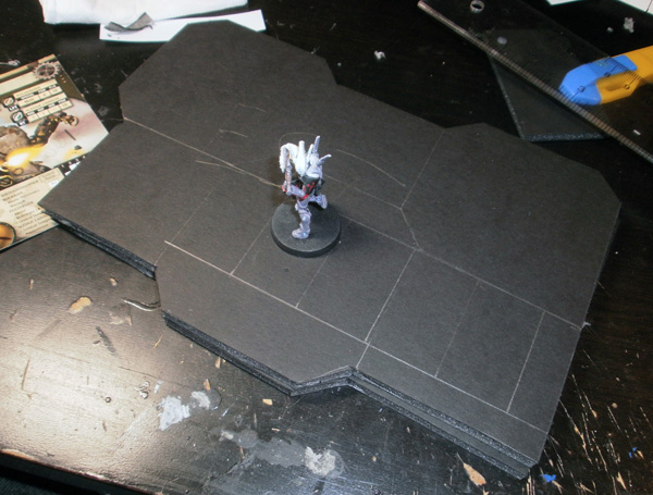
I started by drawing out how much room I had for the stairs, and then marked how deep each one needed to be to let a 25mm base stand on it. This then told me that my staircase could fit a total of five steps; given that I ultimately needed to have them rise a total of 2″, I knew that each would then have a height of about .4″.
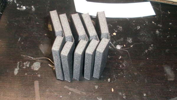
Each of the steps was cut out separately and had a piece cut out to let it fold.

I then rigged up a template in Illustrator to tell me where to place each one.
It’s worth noting at this point that I made a mistake when planning this out. I measured the stairs as if they would be going from the ground to the roof, when in fact they would be starting 1″ up in the air. As a result, the stairs ended up really tall, and the bottom step was actually totally useless. I didn’t realize this until I’d built the first one, which I had to tear apart and reassemble in the correct position; however, at this point I still hadn’t worked that out, so let’s go ahead and watch me do this wrong.
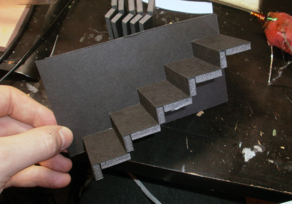
I traced the staircaise silhouette on the side wall of the staircase, then hot glued each step into place.

Here are the two staircases in their miscalculated glory.
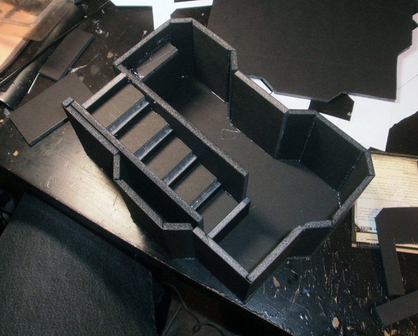
Upon realizing the error, I decided to go ahead and leave one of them as-is– that way I could have one staircase from the ground and one from the balcony, to diversify the terrain set a bit.
So, yeah. We’ve been through this enough times– glue wall segments, then attach stairs.
At this point I’d finished building all of the boxes (though still had some extra pieces to add to a few of them), so I decided to see how they looked laid out together.

I really need to sweep my kitchen floor.
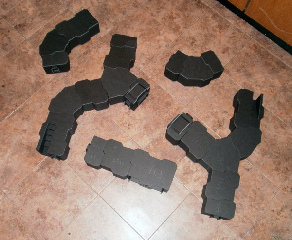
OH EM GEE IT’S SO BEAUTIFUL
;_;
*sniff*
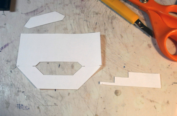
At this point all of the boxes have been built up, leaving only the balconies and staircases to build. As with everything else, I lay out the surfaces and supports for these in Illustrator, print them out, and turn them into tracing templates.

Trace, cut, etc. We’ve covered this.
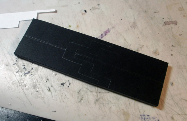
One thing I neglected to take into account on my previous staircases was the width of the foamcore stair surface itself, which leads to one extra-fat stair on either the top or bottom of the staircase. This time around I remembered to include it in my calculation; the top of this staircase, including the top step, would be 1″ in the air, and the two tops of the two steps below it would fall at 2/3″ and 1/3″, respectively.
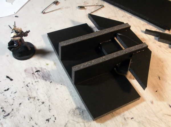
I drew lines onto the bottoms of the platforms to help me line up the supports, then glued them on.
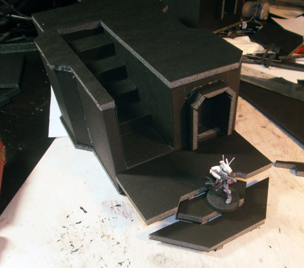
BAM!

Staircase.
*thug pose*
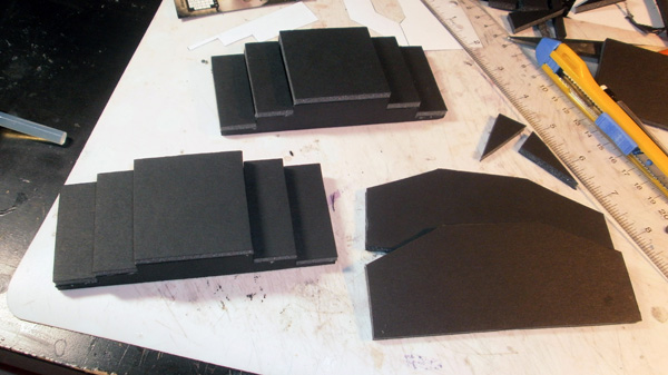
I wanted to have different-shaped staircases throughout the terrain set to encourage a variety of movement patterns, so my next two staircases led left and right out of a door instead of straight outward.

I had to trim the steps for space to be less than 25mm deep, but you can still manage to stand a mini on them for the most part.
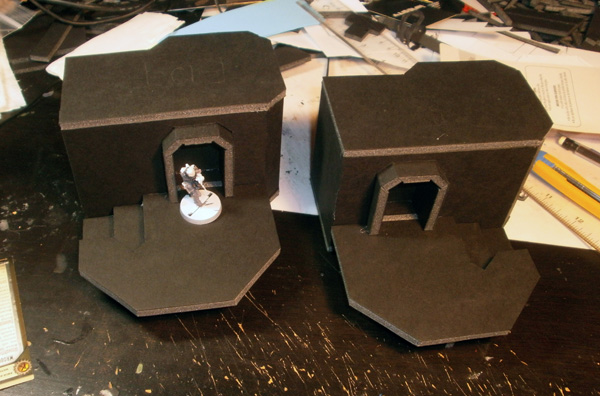
The last two staircases are going to be piled-up cargo storage areas, with staircases that drop down in only one direction.
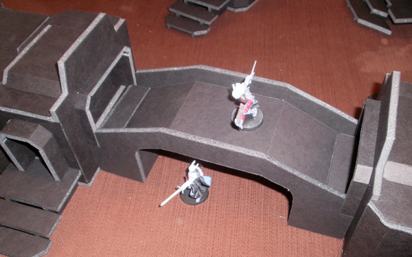
The very last piece to build was the bridge. I had a lot of trouble with this one; in order to get the 1″ of rise that I needed, I had to angle the ends up to a point where models immediately slid down the slope. I tried an alternate arrangement that used stairs, but it was a huge mess and I scrapped it entirely.
Without any better ideas, I went back to the sloped ramp idea, and simply decided that people wouldn’t put models on the sloped parts.
Not the greatest solution, but it’s all I’ve got right now. :/

In order to get the combination of angles that I wanted, the bridge had to be built out of the only two-way bends in the entire terrain set.
It had better appreciate the sacrifices I make for it. >:(
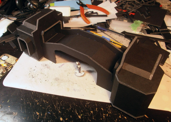
With some sides thrown on around it, the bridge nicely spans a 10″ gap while allowing models passage underneath.
The unusable inclines kind of suck, but I’ll deal with it. :/

The very last pieces to add were the narrow staircases on the sides of the bridge landings, about which I have nothing interesting to say whatsoever.
And with that, bulk construction on Spud’s Foamcore Colony came to a close.

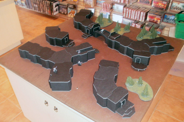
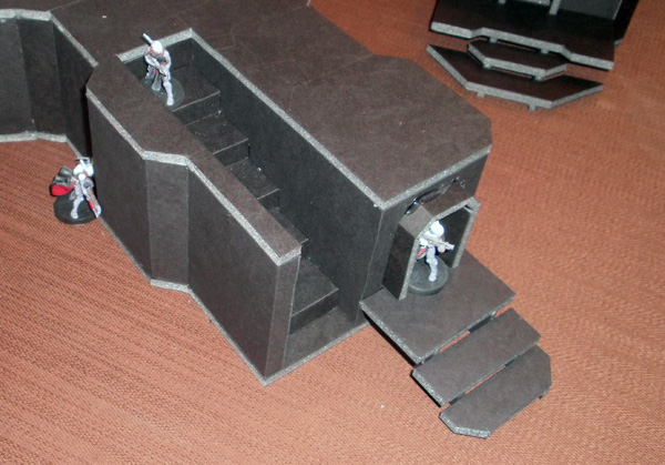
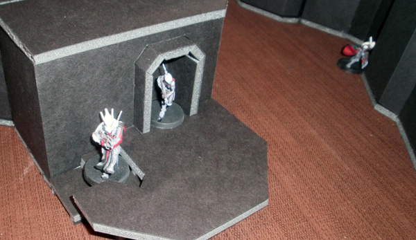

It isn’t totally pretty yet, but it’s playable. Sometimes, that’s enough. 🙂
I’m going to take a break for a month or so to work on other projects, and then I’ll begin Phase 3 of this project: detailing. Every single one of those boxes is going to be completely covered in craft foam paneling, windows, railings, ladders, hatches, elevators, and whatever else is required to complete the effect, and then I’ll need to figure out a way to paint it all without going out of my mind.
My current plan predicts that I’ll have something more to show at some point in November.
We’ll see how good that prediction turns out to be…

Maths!! Looks brilliant, very cool concept and excellent execution.
Work faster.
ZOMG!!!
I saw your thread on the Infinity forums and came to check it out.
1. Captain Spud IS Amazing!
2. Would you consider sharing your Illustrator templates?
3. I LOLd at your writing, keep up the great work.
1) That’s what I’ve been saying all along!
2) Good idea. I’ve posted the templates in Illustrator and PDF formats here: TEMPLATES! IN! SPAAAAAAAAACE!
3) I can’t help it. Great work effuses unbidden from my various orifices whether I want it to or not. Sometimes I wish it would stop so that I can have just a moment of peace, but sadly the universe is not so kind.
Sigh. ;_;
You could glue on some sort of texture, like sand or use textured paint on the inclines so there would be something for the models to grip. Alternatively you could put in strips of detail that are raised slightly to make a lip for the base to grab.
This article contains just soooo much gold! Love it
awesome!