

Do you make really foolish decisions? If you do, and as a result decide to undertake the monstrous labours depicted in this article for yourself, you can find all of the necessary templates here:
- Spud’s YJ City Templates [ZIP, 122k]
I really don’t recommend it, though. You will almost certainly not enjoy the experience.
So without really meaning to, I’ve ended up taking a 5-month break from “real” project blogging. I won’t bore y’all with the details, but suffice to say that a pretty unremarkable combination of “not doing very much” and “not wanting to write about the stuff I did” was to blame. However, in that time I’ve built up a small pile of finished projects, so hopefully I’ll be able to get back into the swing of things over the coming months. 🙂
Without further ado… in May 2017, I posted some designs for a set of Yu Jing urban terrain that I planned to build “at some point”. Quick refresher:
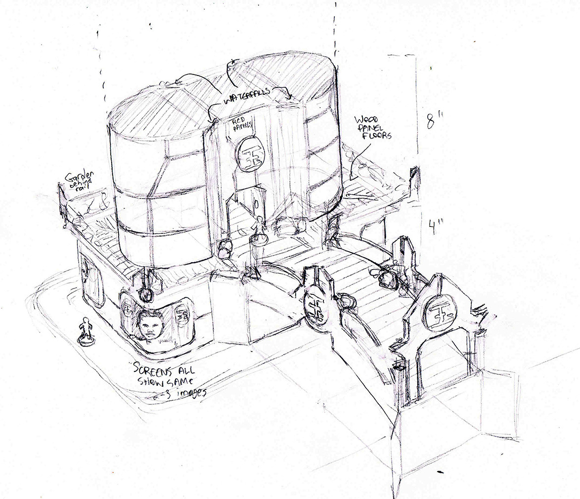

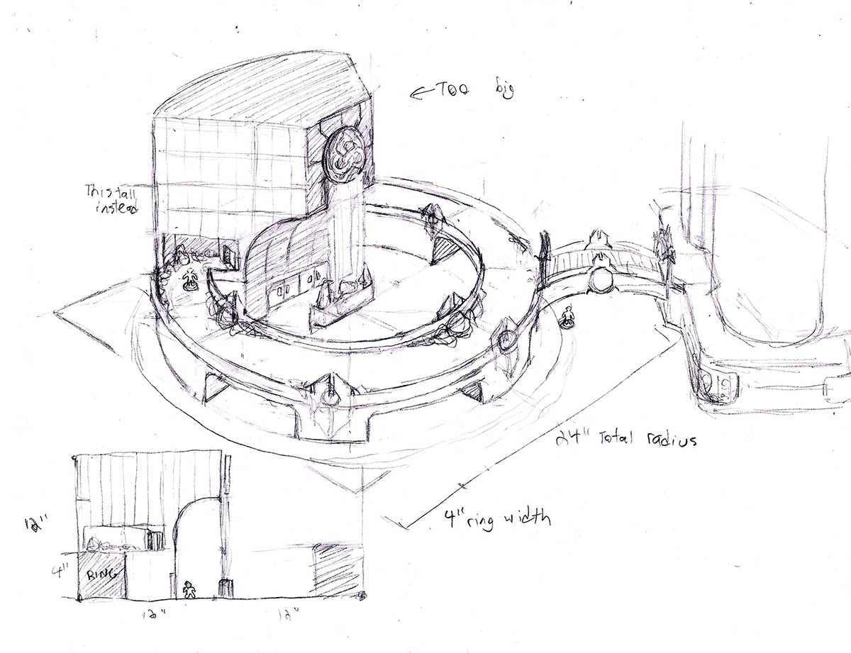
The timeline in my head was that I would do major foamcore construction of the buildings in the Fall, and then take a break for a few months before resuming work on the surface detail in the new year. And for the most part, that timeline has held up– the work you’ll see here was mostly completed in October and November of 2017, and I’m prepping the next stages to start in the next month or two. So, yay for vaguely accurate projections. 😀
The Laser Tangent
However, there was one small bump in the timeline that I did not foresee: after I posted the initial pencil sketches on Facebook, I was contacted by the owner of one of the bigger MDF terrain producers, who asked if I would be interested in having my designs added to their terrain range.
Quick note: I won’t be sharing the name of this company, because this story doesn’t end up reflecting very well on them. So for the purposes of this article, just know that they’re an official Corvus Belli partner, and I’m generally a pretty big fan of their products, despite our unfortunate interaction.
However, continually using vague language is going to get really annoying, so for the remainder of this anecdote, let’s call the company LaserCo, and the dude I’m speaking with will be LaserDoug.
The jaded portion of my brain immediately started holding up warning flags about their offer– for one, they were only offering me free copies of the resulting kits, rather than actual financial compensation for my designs. For another, they still expected me to do a bunch of the work to translate the sketches into laser cut patterns.
However, even knowing that the deal was kind of a turd, I was still interested, for basically one reason: it sounded fun. 🙂 Sure, I wasn’t being paid. And sure, I was essentially volunteering my time to make money for someone else. But I find laser-cut kit design fascinating, and I was willing to get gently screwed this one time if it meant getting to peek into the process from the inside. So despite my reservations, I gladly accepted the offer and started discussing the way forward with LaserDoug.
So as I mentioned above, I was a bit surprised to learn that LaserDoug wanted me to put together the laser-cutting patterns for my terrain set; I had assumed that they would take my drawings and handle all of the technical work on their end, given that actually knew what they were doing. While I’m generally pretty good at deconstructing a 3D design into 2D components, my past experience in this task has always been in the arena of hand-cut foamcore, which is a medium that allows a lot of margin for error. Laser-cut MDF, on the other hand, needs to be laid out with extreme precision, with perfectly-aligned tabs and slots to allow everything to fit together. I mentioned to LaserDoug that I wasn’t confident about being able to make a design precise enough to actually cut out and build; in response, he just sent me a sample Adobe Illustrator file for one of LaserCo’s buildings to show me what was needed.
I’m not going to show you the actual file I was sent since this would reveal the company’s identity, but here’s essentially what I got:
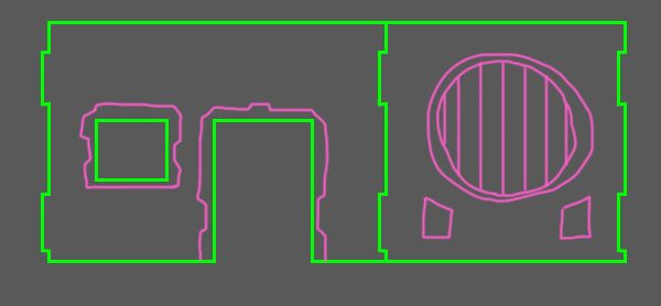
The Illustrator file is full of lines that trace out the various paths that the laser will travel to cut out the kit’s components. Wherever possible, shapes are clustered tightly together so that a single laser line can be used to cut edges from multiple components. The lines come in two colours– green for deep cuts that divide different pieces, and pink for shallow cuts that simply etch details into the surfaces. Shapes within the document are clustered such that they will fit on an A4 sheet; the file they sent me was for a single large building whose components are spread across three A4 sheets of MDF, and another A4 sheet of softer cardboard that can be bent into curves.
I sat down at my computer to start plotting out how my designs would be translated to MDF, but immediately I started struggling with the simple fact that I didn’t really know where to start. Deconstructing the 3D shapes into panels isn’t actually that difficult for me, but I wasn’t sure how best to group the pieces together into sheets. When I make foamcore cutting patterns, I don’t actually care if I’m being efficient with my template layout; even if I end up printing only one panel template per page, the end result is that I consume $2 worth of cardstock printer paper instead of $1.
But for this task, efficient layout was incredibly important, since the costs of the kit to both the manufacturer and the customer are a direct function of the amount of MDF used. However, it was sort of a paradox for me– to draw the lines for a particular component, I needed to know not only the dimensions of the panel, but also the exact positions and dimensions of the tabs and slots that will connect it to other pieces. So it felt like I already needed to know what all of the components would look like and how they would all connect together before I could begin layout out the first piece.
I’ve always struggled with “thinking” directly into a computer. I have a really nice Wacom Cintiq tablet for my computer, but I generally can’t draw on it from scratch– when I try, everything comes out mushy and distorted. Instead, I tend to do all of the sketches for my art in pencil, and only later trace those sketches onto a computer. For whatever reason, my brain needs the tactile feedback of a writing implement in my hand to be able to understand the shapes and forms I’m rendering.
Knowing this, I decided that the best way for me to proceed would be to first lay out the entire project on graph paper, and then start inputting those designs into Illustrator once I knew where everything would go. It took about a week, but eventually I ended up with a pretty complete version of my first building.
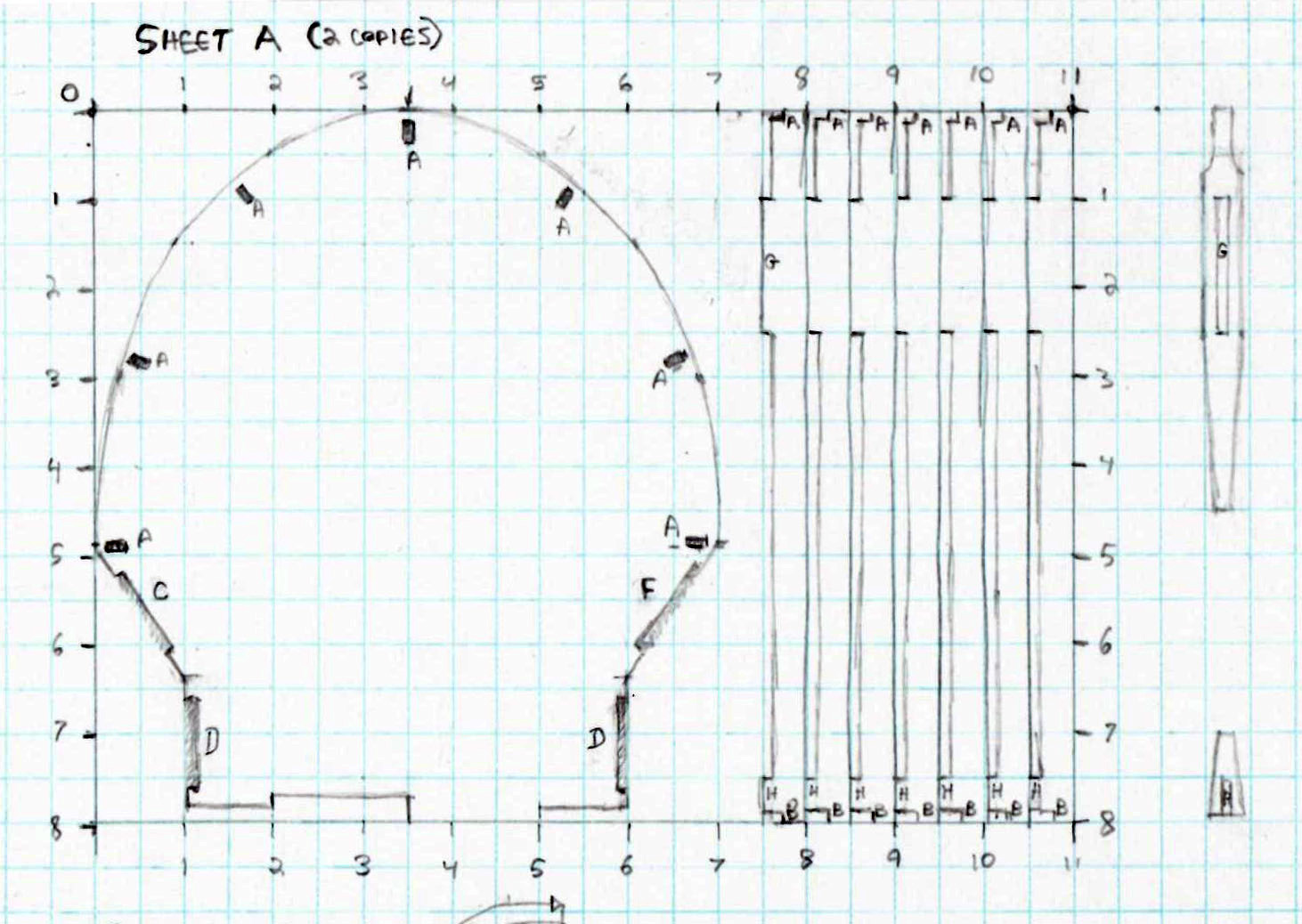
The first sheet is the top of the tower and the seven uprights that hold it up. The “skin” of the tower would be build from soft cardboard (shown on a later sheet), with the clips on the right side used to hold the cardboard down to the uprights. Note that I actually ended up forgetting about the clips after I drew them, never actually allocating them space on any sheet to actually produce. Oops. ~_~
For the drawings, I used a scale of two squares to an inch. I started labeling all of the different joints to indicate where pieces fit together…
…but quickly realized that there were WAAAAY too many different connectors to do this, both because I quickly ran out of alphabet and because it covered the page in too many tiny scribbles. So for the remaining ones, I relied on my own ability to remember how everything links up.
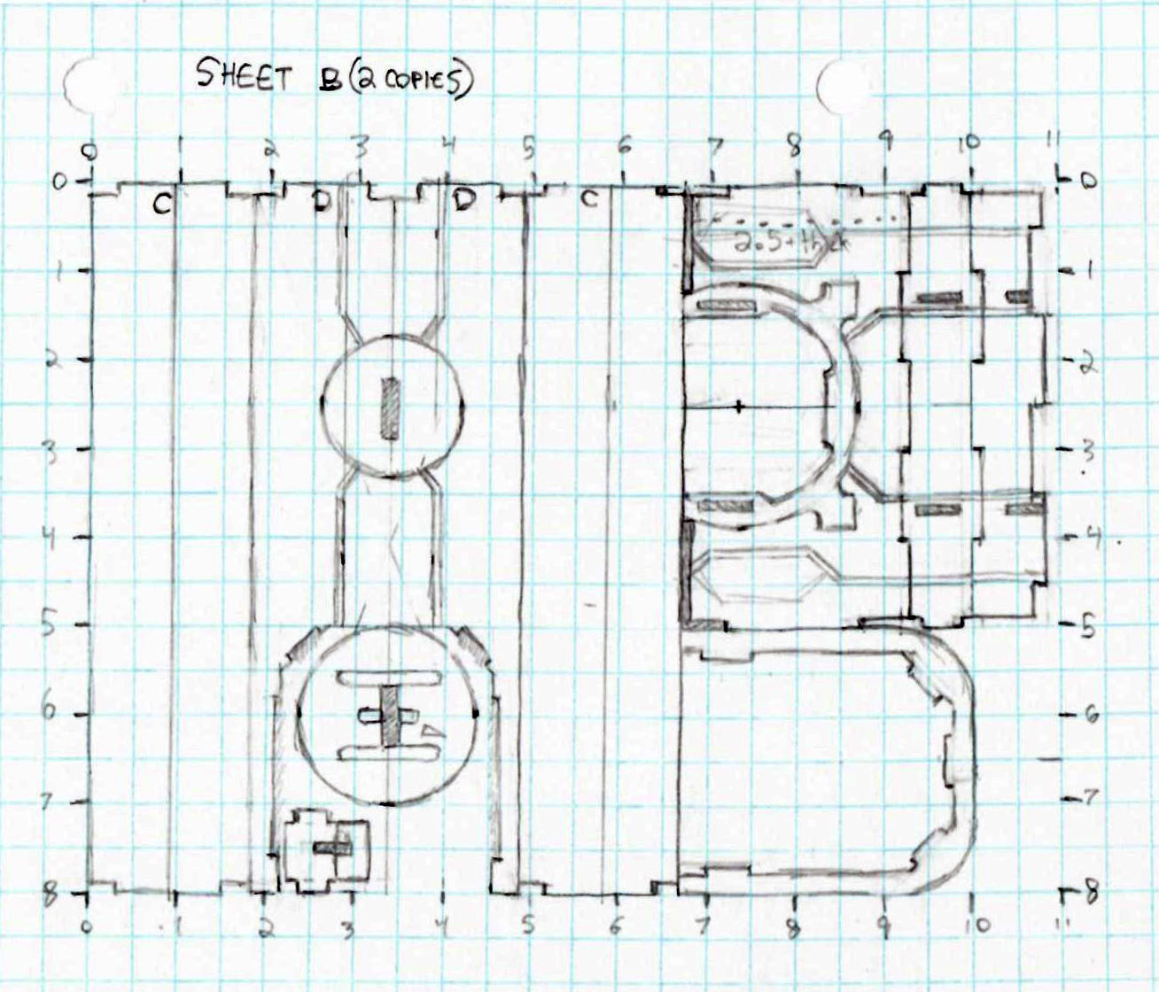
Sheet B is more components for the towers; the left side is the central part of the “hourglass” shape (divided into three panels), while the right side is one half of the tunnel that cuts through it (with the flat panels clipping to the inside of the arch shape).

I labeled it a bit out of order, but this is the bottom of the tower. Since it won’t be visible, I only built this as an outer rim instead of a fully flat panel to save materials; one of the curves pieces is fully intact, while the other (placed on the inside) had to be broken in half and would be glued together by the customer. The bottoms of the tower uprights then slot into the holes in this outer rim.

The next few sheets make up the building’s base. This sheet contains the wood-plank panels that will be the base’s walking surface.

Sheet D contains two of the base’s longer upright panels, as well as the base supports for them. I tried to keep each segment’s upright and base together to make assembly easier.

These are the two “bumps” on the base onto which bridges could be clipped.

This is a bit of a catch-all sheet, with round sections of the base, one last “bridge bump”, and a number of internal supports that would hold the base together (if none of this is making sense to you, there’s a sketch a few pictures down which shows how the pieces go together).

The last two sheets are intended to be printed on soft cardboard instead of MDF. This one contains the 3/4″ tall railings that would fit around the top of the base; these only required half the sheet.
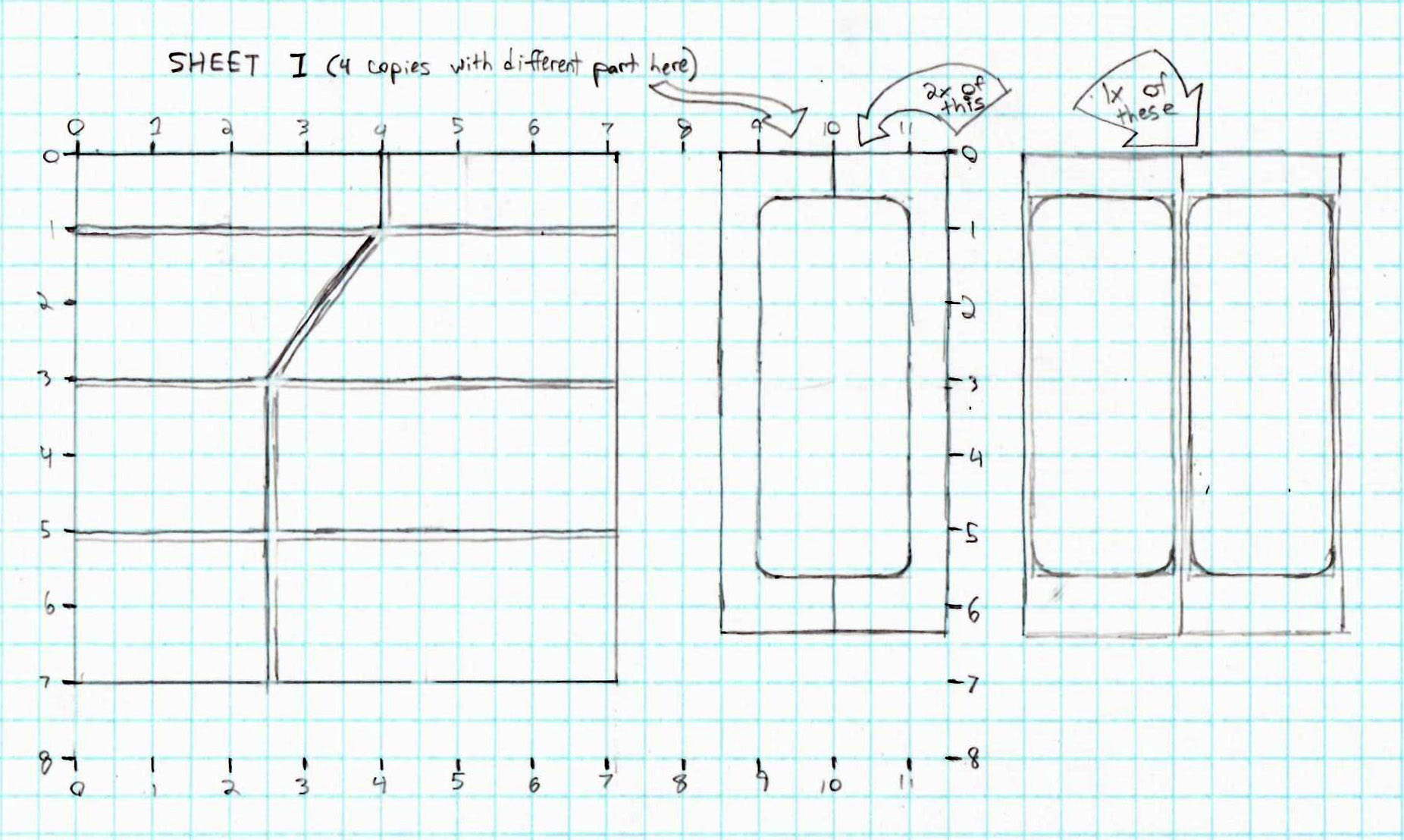
The second cardboard sheet contains all of the curved wall sections. Two of the panels at left combine to cover each side of the tower, while the bits at right are the curved panels for the bases (the bigger one is a frame with the center cut out, while the two smaller ones are a backing that sits a smidge behind it– with the intention being that LaserCo would also provide a colour printout of a TV screen to sandwich between them).
As I was laying out the panels for the base, I made a new sketch to help me keep track of where all the pieces go:

By the end of my Week of Scribbling, I had a pretty complete picture of how to deconstruct my design into panels, and how to tesselate the panels onto A4 sheets. My hope had been that I would have enough to work with at this point to let me proceed to building things on the computer, but instead, the entire process had filled me with doubt about whether any of this would even work. The design I had come up with required 10 sheets of MDF and 4 sheets of cardboard, which would make it an enormously expensive kit to purchase (I calculated it at somewhere around $130 per building). And even then, I wasn’t sure if the mostly hollow construction I had laid out (with outer rings on the bottom of each piece instead of full flat panels) would even be strong enough to stay intact.
I e-mailed LaserDoug with my concerns, and he replied…. nothing. Since he first reached out to me, LaserDoug had proven to be very slow to return e-mails. This was especially problematic given the minor language barrier involved (as LaserCo is not based in a primarily English-speaking country), as I often wanted clarification on awkward translations and had to wait several days each time to hear back. After my “I’m not sure this is going to work” e-mail, I heard nothing for over two weeks, so I concluded that LaserDoug was discouraged enough by my concerns to lose interest in the project. I e-mailed him again to state as much, and told him that I was going to go ahead with building the board myself and then releasing the plans through my website.
Almost immediately, LaserDoug e-mailed back, saying that he had replied to the previous e-mail but that something went wrong with the delivery and it didn’t arrive. He said that there had been some delays on his end due to other projects and some family drama; he wasn’t concerned about the needed materials, and my pencil layouts would be enough for him to work from. Relieved, I told him to let me know when he was ready to pick the project back up.
That was in late June, and was the last time I heard from LaserDoug. It took me until October to conclude that this arrangement wasn’t going to go anywhere, at which point I shrugged and returned to my original plan of building everything out of foamcore.
In the end, I have mixed feelings about my interactions with LaserCo– I’m really annoyed with their lack of professionalism and communication, not to mention the fairly terrible deal they were willing to offer up-front that I would not have accepted but for my curiosity. However, I did still get the peek I wanted into the laser-cutting world; I learned a ton from looking over the Illustrator file they sent me, and would feel much more confident about creating a (smaller) design for another company in the future if that opportunity ever came up again. And while the time I put into my graph paper designs didn’t ultimately yield a commercially available kit as I’d hoped, I wouldn’t say it was wasted either. The deconstruction process helped me to flesh out the design, and made the subsequent process of template-making for foamcore construction go much faster, since I already knew the panel layouts inside and out.
So, yeah. Weird thing happened, people kinda suck, weird thing didn’t really go anywhere, life goes on.
*shrug*
Really great work again. It’s a shame lasdough was such a waste of time and effort. Keep on the good work, will look great at the end i’m sure.
PHWOAR! What awesome terrain, and incredible insights! Inspiring stuff, Spud!
Very cool!
I felt distinctly masochistic recently and decided to try my hand at the ring and ISS tower. So far it’s been a mixed success completing the ring, however, on the base segment for the final quadrant of the ring I can’t seem to find the template in the downloads. Am I missing something?
1) Dear God, why are you doing this to yourself? I TRIED TO WARN YOU! I TRIIIIIIIIEEED ;_;
2) I’m looking over the template files, and it looks like the footprint for the ring tower is built out of two other templates:
That definitely wasn’t clear from the templates or the walkthrough. Potato bad at instructions. 🙁
3) Let me know if anything else is missing or unclear. 🙂
Haha I excel in making poor decisions.
I thought it might be something along those lines but didn’t fancy gambling the time and resources on the hunch. Thanks!