
2017
In the 18 months following the shelving of the space station set, I don’t think I ever once had the thought, “Man, I should totally finish that set. It could have been so awesome.” That’s usually the thought process that brings me back to an abandoned project, but in this case it never happened. I have seven other terrain sets, and I did not feel a space-station-sized hole burning within my collection.
However, as I mentioned at the start, something did eventually prompt me to reopen the plastic bin of space station walls– the Strikezone Wotan global mission that ran this past spring. This league was primarily set on a series of space stations and ships, so having a space station terrain set to play on would be very thematically appropriate. I remained fully conscious of the factors that had left me to shelve it– a fuzzy idea of where to go next, mechanical problems that made the board awkward to use, and a general lack of interest– and really, nothing had changed on any of those counts. I still wasn’t really that interested in picking the project up again, but I decided to force myself to do it just to wrench myself free of the motivational dead zone I’ve been in since last November.
Basically, “I’m not going to like it, and it might not turn out well, but DAMNIT, I AM A PERSON WHO MAKES THINGS, AND I’M TIRED OF NOT MAKING THINGS, SO I AM GOING TO MAKE THIS THING.”
As rallying cries go, it wasn’t the best. But it was enough.
Looking over the pieces I had from 2015, my set consisted of:
- Some walls (but not enough)
- Some couplings (but not enough)
- Some very rough, always-intended-to-be-temporary styrofoam walls with doorways cut into them
- A two-panel semicircular platform
- Two cargo tubes (that don’t really connect properly to the board)
Which left me a to-do list of:
- More walls
- More couplings
- Walls with doors in them
- Outer walls
- Airlocks
- Some way to link the cargo tubes up with the interior
- Paint, papercraft, and whatever else needs to be done to pretty things up
That’s… a fair bit of stuff.
Oy. :/
The best way to jump-start the project’s momentum would be to dive in and finish something in one day, so I decided to start with something I thought I had planned out pretty clearly: the airlocks. However, all of my plans were in my head, and they turned out to be:
- incomplete, and
- kinda bad
I knew some things about how I wanted the airlocks to work: I wanted them to be rooms that could be placed along the outer wall, with a door on both ends. I wanted the doors to slide up and down. And I wanted Infinity models of any valid silhouette size to be able to fit through. All of these design goals were good ideas, and with some time spent concepting, there was easily a great airlock design waiting to be found within them.
However, I didn’t want to do that, so I made bad airlocks instead.
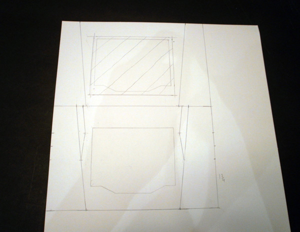
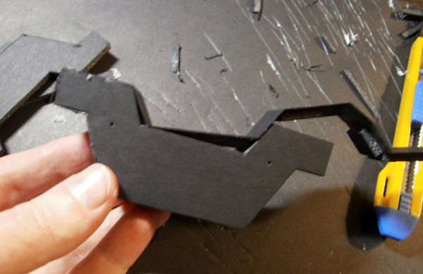
The next bit will be hard to follow without an idea of what I’m building, so here’s an after-the-fact MS Paint drawing of the design for the doors:
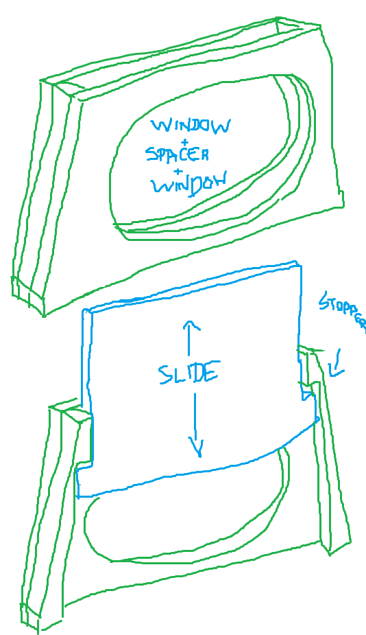
So basically, each door is three foamcore sheets thick, is shaped like a trapezoid, and has a pill-shaped doorway.
If I had drawn concepts, I would have realized that a trapezoidal airlock shape (fat at the bottom, thin at the top) is really complicated to link up to a surrounding wall set. I also would have remembered that rounded rectangles are present in precisely ZERO of the other components of the set, making them a complete visual mismatch. I would then have realized that I already had a very similar (and much more badass) visual element in the octagonal cargo tubes, and could easily have copied that shape here to build a consistent visual language for the set.
That isn’t what happened, though.
I did no concepts, so I didn’t see the problems until I was finished, and now I am a broken wad of regrets. ;_;
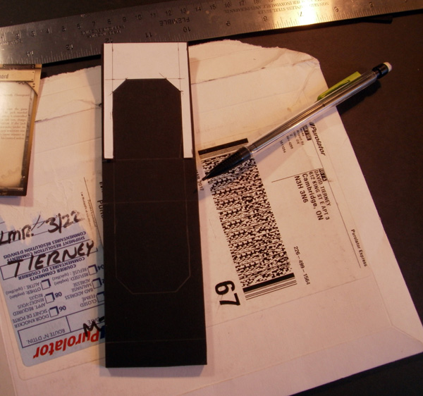
Alrighty, let’s commit bad ideas to paper!
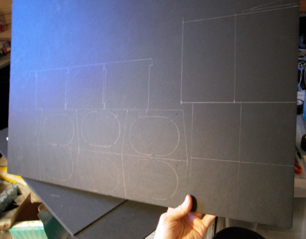
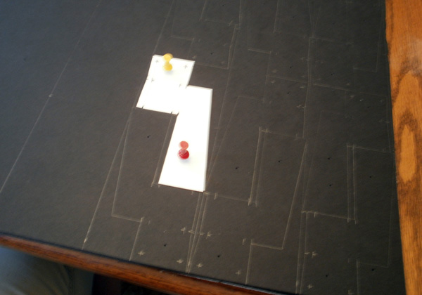
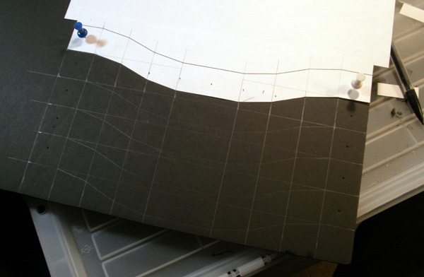
The templates seen earlier were drawn in Illustrator, then printed and transferred to a sheet of Foamcore.
I cut out enough pieces to make two airlocks, which seemed like enough access points for a 48-inch outer wall.
I wanted the doorways to open as close to the ground as possible, so I cut out the foam from the edges of the floor piece to let me sink the doors an extra 1/4″ lower.
Hey look, it’s another bad idea!
I planned to apply papercraft textures to both sides of the door, and figured that this would make the door too fat to sit between two foamcore sheets. To solve this “problem”, I added the width of one sheet of craft foam to each spacer piece, increasing the width of the the gap between windows by 1/16″.
Somehow during all of this, it never once occurred to me that paper is really thin, and there was no problem to solve here. So now, several months later, I have too much space between the layers, and the door isn’t held in by pressure, and it always falls down.
YAAAAAAAY!
~_~
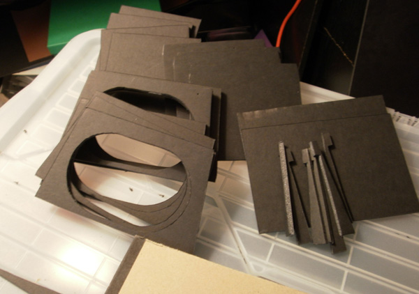
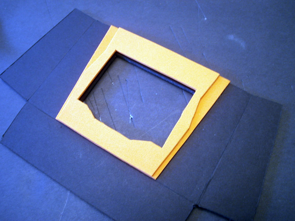
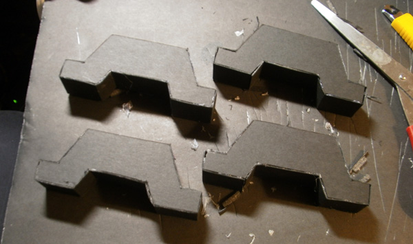
So anyway, I built four doorways (two per airlock) by sandwiching the spacers between the outer window pieces.
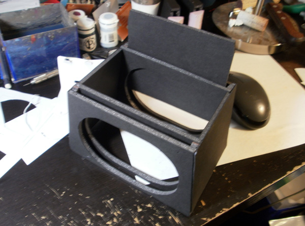
The sliding doors were then loaded in from underneath, and everything sat down on top of the floor panel (not pictured here).
There’s more work still to do on these, but at this point I moved onto a different task, so we’ll revisit them in a bit.
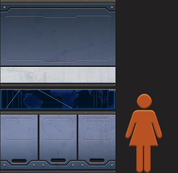
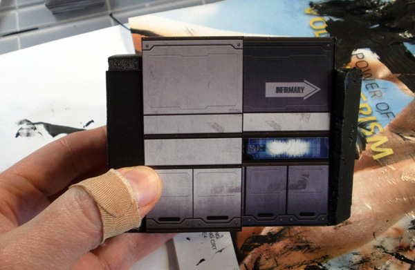
At this point, all of the walls in my space station were plain black foamcore. I had had extremely good results with custom papercraft walls when building my space ship, and had always intended to carry that technique forward to the space station. However, I didn’t want to just reuse the same wall patterns again, so I sat down in Photoshop for a few hours and knocked out a custom wall panel design from scratch.
Out of all of the regrettable improvised design mismatches in this terrain set, this wall pattern is probably the second most successful (after the incredible fluke of brilliance that was the Spud Curve, of course). My terrain set had four different lengths of walls– 2″, 4″, 6″, and 8″– and would eventually have variations of those with walls cut into them. I needed the wall texture to work in any of those wall lengths, and still look good when repeated over twenty-plus total feet of wall space.
I accommodated these needs by creating a 2″ wide panel design, with a one-third subdivision over part of it to break up the regularity of the vertical lines. I placed the various panels in locations that seemed vaguely plausible to me– the lower panels have handles to let them be pulled out to access any tech stuff running inside the walls, and screens were placed at eye height (which is perhaps a bit too high, now that I’m thinking about it).

Once I had my basic panels, I duplicated them across a full 11″x17″ page, and differentiated the panels by swapping out the computer displays, adding a variety of “tour guide arrows”, and labeling the contents of the lower panels.
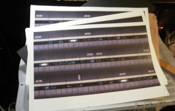
As usual, I will happily give a plug to Staples Print & Copy Centre, which prints full-colour 11×17 sheets for like… eighty cents. Enough papercraft to cover the entire set was five bucks. I… I just love Staples so much, you guys. ;_;
(Let it be known: Spud’s love is for sale, and the price is “five dollars worth of laser printing”. <3 )
(Let it also be known: there’s a zip file with printable versions of all of this project’s papercraft elements at the end of the article, so that you can cover up your bad decisions with attractive wallpaper, JUST LIKE SPUD!)
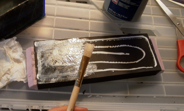
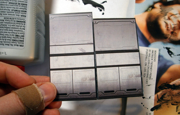
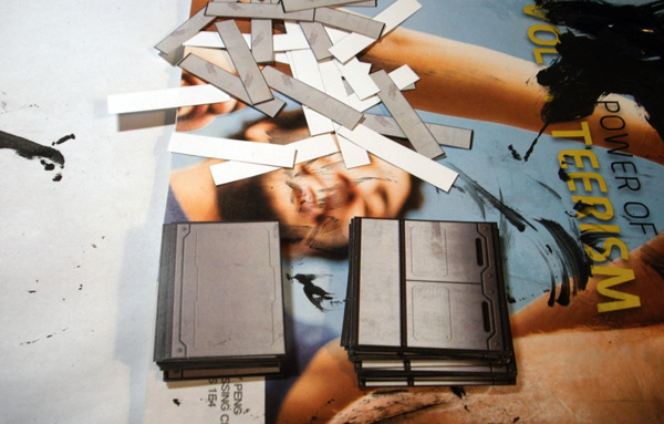
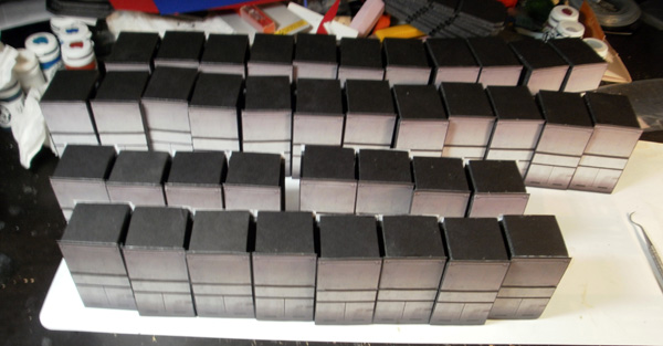
I cut the printing into strips, and the then prepped the wall pieces to have them stuck on by applying white glue and brushing it flat.
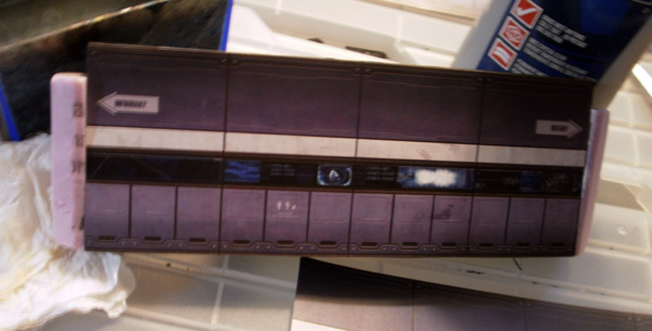
This helps prevent the papercraft from buckling when it touches the glue, ensuring it dries smooth.

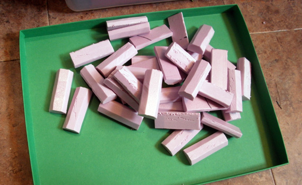
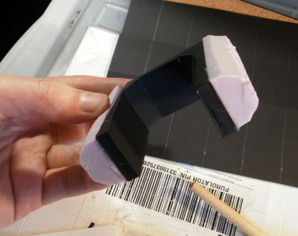
It occurred to me after doing the first one that the ends look kind of stupid when left pink, so I painted them all black and covered them with Mod Podge as a sealant before sticking on the remainder of the walls.

The 2015 build of the space station used very rushed hole-cut-in-styrofoam door segments that looked bad and lacked the heft of the solid wall pieces. With the wall segments finished, it was time to replace the styrofoam doors with proper foamcore ones.
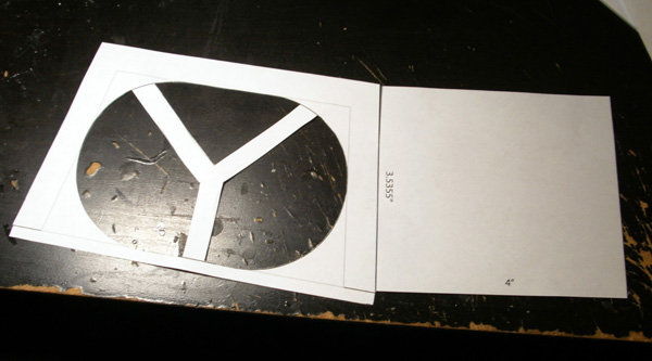
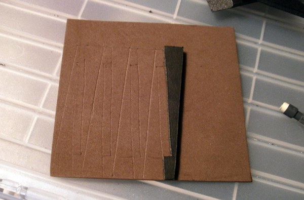
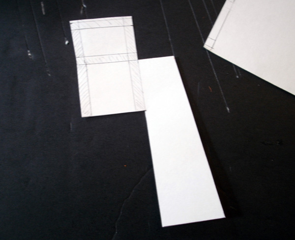
To start, I got out a piece of card stock and laid out patterns for a narrow door that fits within a 2″ space (and is tall enough for all 25mm silhouettes), and a wide door that fits within a 4″ space (and is tall enough for all silhouettes except the Maghariba Guard’s S8).
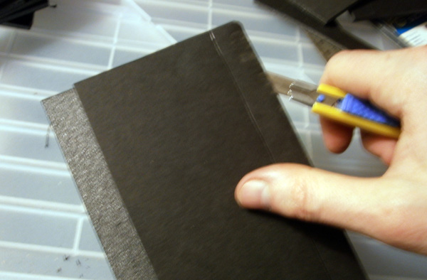
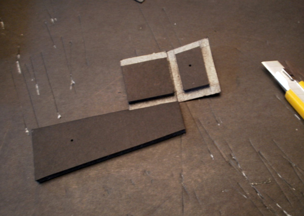
Next, I cut out another set of foamcore wall segments, and traced the door patterns over them.
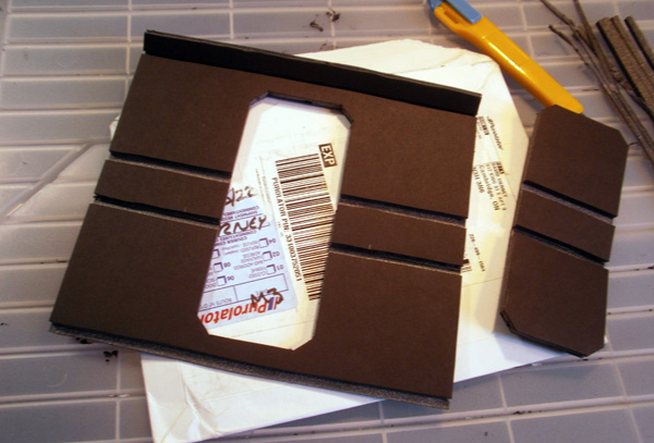
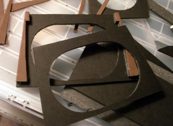
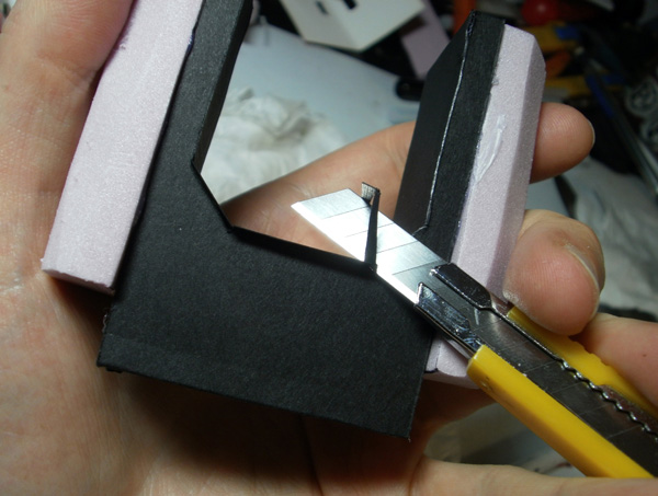
The doors were then popped out with a knife…
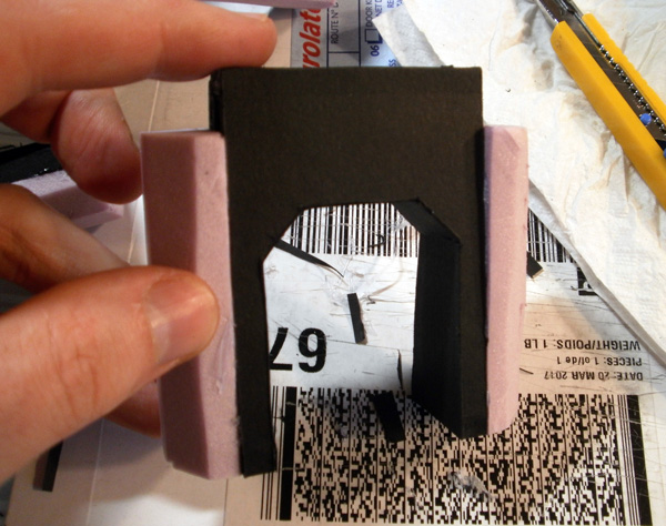
…leaving these nice archways. Wherever possible, I tried to leave enough space on either side of the door to enclose weights within them as I had done with the walls.
This wasn’t always possible, though. The 2″ mini-doors would need to rely on the ballast of their adjacent wall segments to keep them in place.
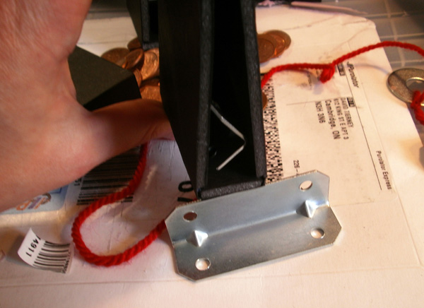
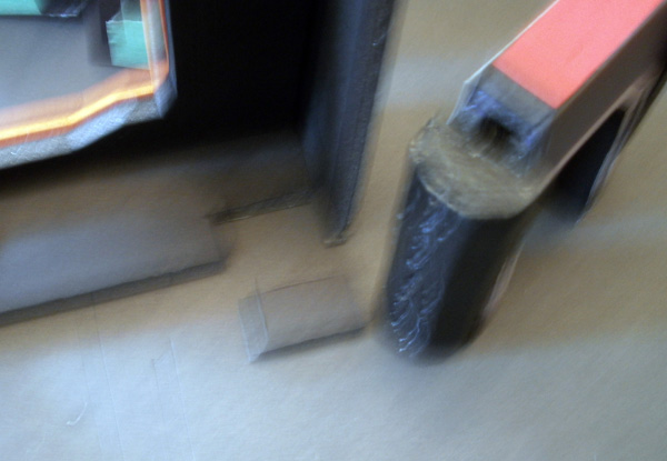
I couldn’t find the bag of rocks I had originally used for weights, so I scrounged around my apartment for other things I could use as weights. These L-brackets turned out to be perfect for the very large 8″ walls with 4″ doors, sliding in snugly in the space on either side of the gate.
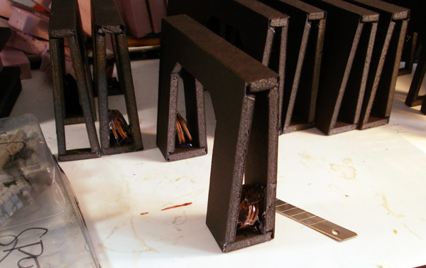
For the narrower pieces, I glued in bundles of pennies, which had recently been obsoleted here in the Fabled Canadas.
I then cut out a bunch more end caps, and stuck them to the sides of the wall segments.
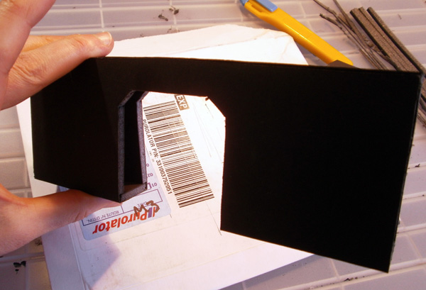
The last task was to close the interior surface of each gate. I couldn’t pre-plan a specific piece of geometry to perfectly sit in the opening for every piece (starting at 1″ wide at the bottom and then narrowing toward the top of the archway), because each one was glued together with a slightly different slant and the angles would rarely line up. Instead, I cut a 1″ strip of black cardstock and scored it to fold at the right points to fill the entire interior.

This left an overhang toward the top, but that was easily corrected with a quick shave:
The cuts ended up a bit ragged, but I doubt anyone but me would notice. 😛
Ta-da!
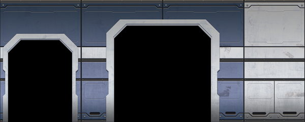
I wanted the gates to match the walls, so I made a modified papercraft skin for them based on my wall panel design from earlier. The white segments were intended to fit over the various coupling pieces.
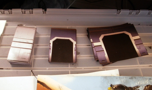
These were then cut out…

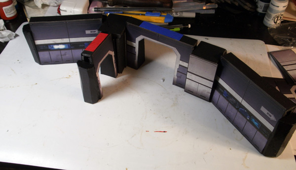
…and glued into place. By keeping all of the wall segments to even multiples of 2″, I could simply tile wall and door papercraft panels next to each other without needing to make specific full-width papercraft skins for each length of door segment.
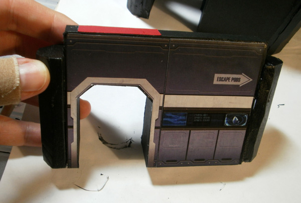
As an added touch to help board legibility, I glued a paper strip to the top of each doorway to indicate its location and width. Narrow red strips for narrow doors, and wide blue strips for wide doors. Once the board is assembled, these strips let you plan paths through the station from overhead, knowing at a glance which doors your larger models will fit through and which they won’t.
Next, I moved on to gluing the white panels onto the couplings. However, I immediately ran into a problem: they were too tall. While the wall segments were 3″ tall, the foam end pieces were a half inch shorter. Even with an extra foamcore sheet’s width added on top, the couplings were still only about 2.75″ tall, leaving the white strips improperly sized to fit them.
This is one error that I won’t chalk up to lack of concepts– rather, it was simple inattention when trying to quickly knock out patterns over a lunch break at work. :/
Fortunately, there happened to be a relatively straightforward fix– the second panel from the top was almost the exact size of the excess height, so if I removed that strip, the remaining panels fit the couplings quite nicely.
So while this error required an extra half hour of scissor surgery…
…and also prolonged the gluing process (since there were more pieces to attach), the end results still looked pretty good.
With that, the interior walls were pretty much done, but I still needed to build the outer walls that divide the habitable area from the vacuum of space.
First off, let’s take a moment to appreciate that I’ve created ANOTHER window shape that doesn’t match anything else in the terrain set, because consistency is for smart people. ~_~
The templates for the outer walls involved a lot more math than the interiors. I wanted the outer face of the walls to be slanted back (so that the angle between the outside floor panel and the upright face of the wall was wider than 90 degrees). To let these walls connect to the interior ones, though, the interior face of the outer walls needed to be a square vertical. This led to the fat-bottom-narrow-top shape on the left side of the template here.
On top of that, the outer walls needed to have a slight wedge shape when viewed from overhead so that they could link cleanly together while forming a smooth arc. I figured out the angles required for this in Illustrator, which resulted in the trapezoid at the bottom.
These two angled bits were relatively straightforward.
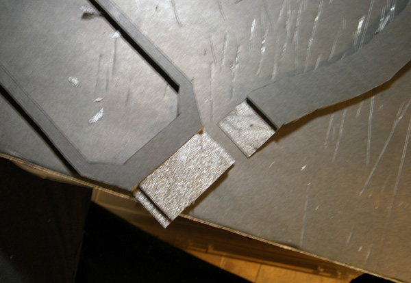
This bit, less so.
This is the end cap in the interior side of the outer walls. The middle panel sits above an empty void, which is sized to accept the styrofoam linkage from any wall segment. The section at the top folds down to make the top of the wall, and needed to match the “overhead wedge” shape of the wall’s base. The bit on the right folds in to form the side of the empty slot, and needed to match the incline of the outer part of the wall.
I really hope some of that made sense. >_<
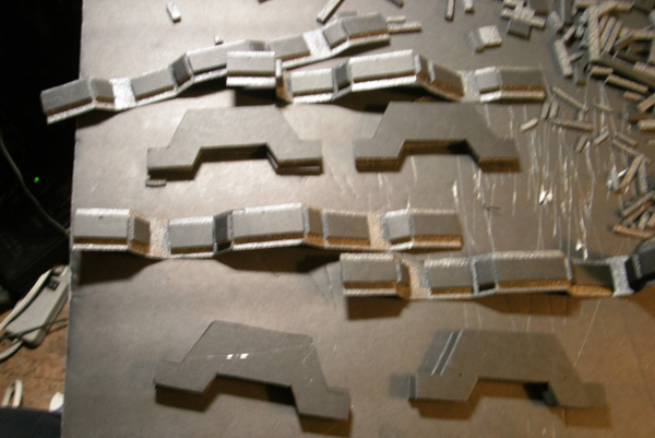
I had created six outer wall segments– each six inches long, which when combined with the six inch airlocks and some extra filler bits that we’ll see in a sec, would form a slightly-more-than-48″ arc to cover the table.
Each wall needed two of these segments, one in a flipped-over orientation from the other, which Grade 2 math tells me adds up to 12 total funky end caps.
The folding cutouts for these pieces were a pain in the ass. >_<
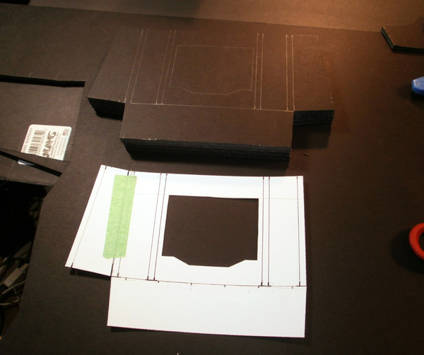
Holes had to be cut in the Outer Wall Floors to accommodate Interior Wall End Caps.
The component nomenclature for this project is starting to get a bit tangled. :/
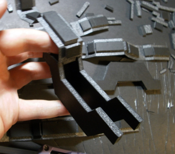
Once folded and glued, these completed the geometry for the outside walls to let them link side-by-side with other wall segments, as well as fitting in with the connection slots for the interior walls.
HEY WAIT SPUD WHAT’S WITH THE ORANGE PARTS
Oh, right. I had to shuffle the order of these pictures a bit to help the writeup make more sense (yes, that’s right, it somehow originally made LESS sense than this!), so let’s jump back a day or so to the window panels.
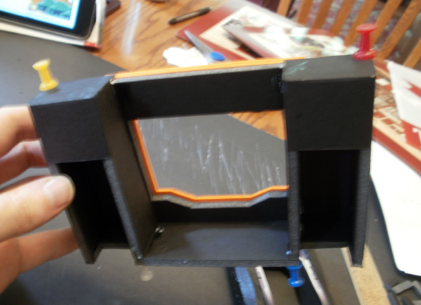
I had always intended to feature use sheets of mirror scrapbooking paper to create the station’s outer windows. I planned to have these windows attach to the outer face of the exterior walls, sitting within a window frame slot created to hold them. Here I’ve created a layout for the outer face of this frame (bottom) as well as the spacer piece that would actually sit around the reflective paper (top).
I glued these two pieces to each other, attaching them for now only from the top. After I painted everything, I could lift the frame, place the reflective paper inside it, and then glue the remaining edges down.
Hey, remember those clumsily assembled airlocks I built before?
Those needed to link up to the outer walls. But since I had built them with a trapezoidal shape, getting them to link up correctly to the already-beveled-on-two-axes outer walls required a connective piece with angles in every single axis of space!
Which resulted in these godless abominations, which took thirty years to math up and assemble!
*sounds of insonsolable weeping and possible self-harm*
Oh, and as long as we’re on the subject of awkward kludge solutions to preventable challenges, remember those cargo tube things from like 70 pictures ago? Whenever we had played on the terrain set in 2015, players were confused about how they were supposed to use those, as they didn’t really connect to anything on the interior of the ship. I really loved the cargo tubes, so I wanted to create a piece that linked to them to make them a more integral part of playing on the board.
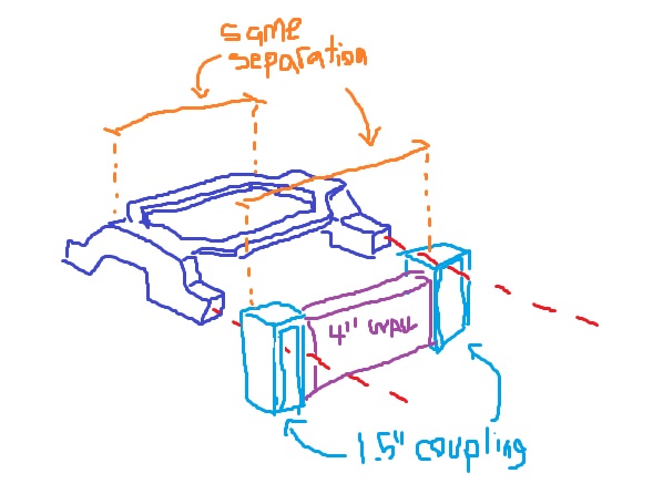
(I didn’t take great pictures for this next part, so I’ll provide another after-the-fact MS Paint sketch for what I was trying to build)
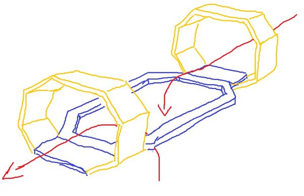
Alright, so the basic idea here is one of several “drop-off-points” within what I imagined to be a long cargo tube. Cargo intended for other areas of the ship would pass right by, but cargo meant for this particular area of the ship would slow down within the horizontal anti-gravity track and then drop down within the frame by way of a perpendicular grav-lift. Reusing the identical Spud Curve octagons on the ends helps visually reinforce that this elevator is connected to the outer tubes.
The end rings were built with the same template as the outer tube…
…and the elevator frame is a simple flat sheet of foamcore. The ends of the two pieces were stripped and then glued together.
The only really interesting part of this piece is the method by which I made it connect to the rest of the board, which turned out to be yet another flub in a project full of them.
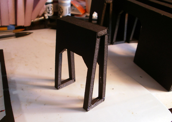
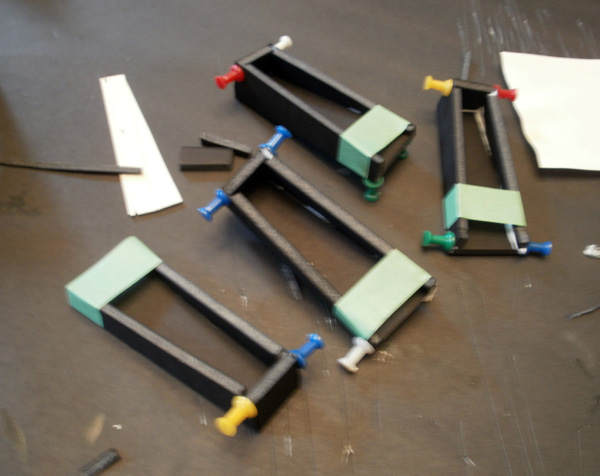
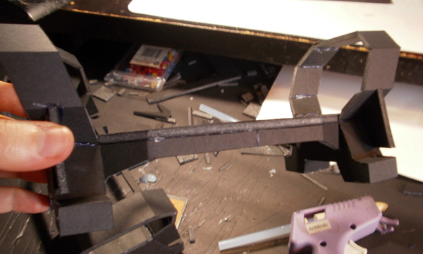
So, here are some things. I made two elevators (one for each cargo tube), and each one needed an elevator at each end. To make them connect to my wall pieces, I built these sawhorse-shaped pieces, which would sit underneath the cargo elevator’s horizontal frame and then slot into the wall couplings with the lower tabs.
I could have built these quite quickly out of insulation styrofoam, but instead I decided to spend many hours designing and assembling them out of foamcore, because reasons.
Reason #1, I suppose, being “I just kinda enjoy making foamcore things.”
Once they were built, all I needed to do was glue them to the frame. Since these would be at a fixed distance from each other, I needed to ensure that they were precisely spaced to link up nicely with my fixed-size wall pieces, like so:
But because this article’s theme is “no planning = garbage outcomes”, I did not actually think that hard before attaching the sawhorse pieces. Instead, I thought to myself, “I have six-inch wall pieces, so I’ll put them six inches apart.” Completely ignoring the fact that my couplings ADD EXTRA DISTANCE when they clip onto things.
So, yeah. The final hard-locked separation I created for the cargo lifts was too close together to attach to a six-inch wall, but too far apart to attach to a four-inch wall. This necessitates some really awkward wall layouts when I assemble the board now, all because I didn’t bother to think things through before I glued them together.
BUT SPUD YOU CAN MOVE THEM
Technically true, but it’s not quite that simple:
The final pieces have a bunch of extra foamcore pieces connecting the rings to the sawhorses, so I would need to cut through a LOT of attachment points and possibly break the foamcore in order to free them up, and then probably slice through that vertical skirt under the elevator frame to make room to slide the sawhorses inward.
All of which is do-able, but I haven’t done it yet because I’m super discouraged about the project and haven’t really had the heart to dive into modifying it yet.
*sigh*
STILL NOWHERE NEAR DONE THOUGH!
LET’S GO AWKWARDLY F*** UP THE FLOOR!
Really a great project!
I’m already looking forward to your next table project 🙂
Don’t be sad, great result!